 |
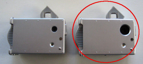
 Important note: This modification instruction applies to all VistaQuest VQ1005 after late 2008 (right model). Easy way to distinguish "new" from "old" is the diameter of the lens hole. With the late 2008 model the hole was increased from around 1/4 inch to 1/2 inch.
Modification instructions for the old model can be found here.
Safety note: Please work always with precaution. The camera can be damaged with electrostatic discharge. Touch only parts which you have to.
Never apply more force than necessary.
|
 Wichtiger Hinweis: Diese Umbauanleitung ist gültig für alle VistaQuest VQ1005 Kameras ab Herbst 2008 (rechtes Model). Ein einfacher Weg zur Unterscheidung ist der Durchmesser der Linsenöffnung. Ab Herbst 2008 wurde dieses von ca. 5mm auf 10mm vergrößert.
Umbauanleitung für das alte Model findet sich hier.
Sicherheitshinweis: Immer vorsichtig arbeiten, die Kamera kann durch statische Entladung zerstört werden. Nur das anfassen was unbedingt sein muss.
Nie mehr Kraft aufwenden als unbedingt notwendig.
|
 |
|
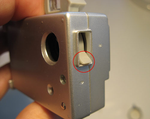
Step 1 - Bring the focus lever in a defined position before opening the camera.
|
Schritt 1 - Den Fokus-Hebel in eine eindeutige Position bringen bevor die Kamera geöffnet wird.
|
 |
|
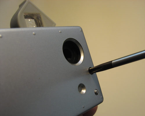
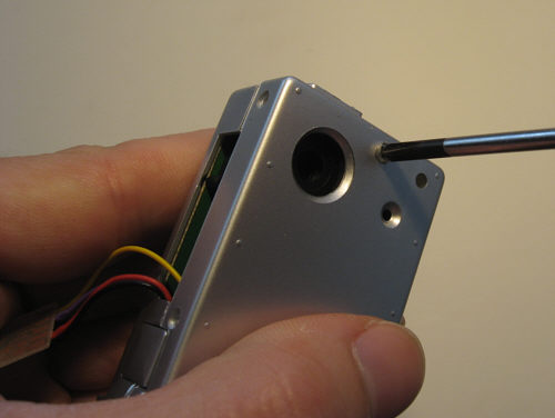
Step 2 - Loosen long screw from front side.
|
Schritt 2 - Die lange Schraube auf der Vorderseite lösen.
|
 |
|
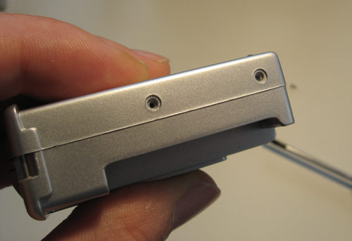
Step 3 - Remove screws from camera bottom and top (4 screws in total).
|
Schritt 3 - Schrauben am Kameraboden und an der Oberseite lösen (4 Schrauben insgesamt).
|
  |
|
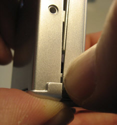
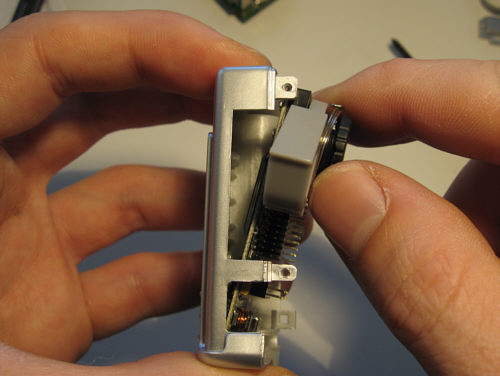
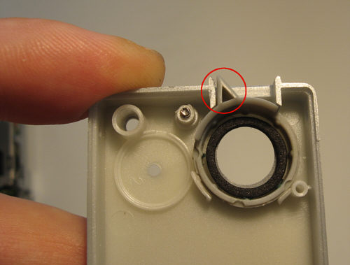
Step 4 - There is a lock latch hidden near the keychain bar. You must press down on the backside of the camera enclosure as shown above in order to release the latch. Pull with the other hand the front side of the camera enclosure.
|
Schritt 4 - Es gibt ein versteckte Sicherungslasche die das einfache Öffnen des Gehäuses verhindert. Nahe der Aufhängung für den Schlüsselanhänger muss die Rückseitenteil des Gehäuses wie im Bild gezeigt nach unten gedrückt werden. Gleichzeitig mit der anderen Hand die Vorderseite des Kameragehäuses ziehen.
|
 |
|
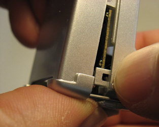
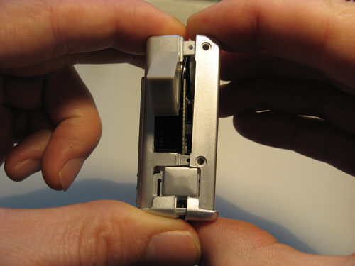
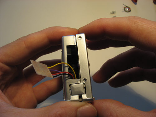
Step 5 - The front half of the enclosure can now get removed by pulling it appart from the backside.
|
Schritt 5 - Die Vorderseite des Gehäuses kann nun durch Auseinanderziehen entfernt werden.
|
 |
|
Step 6 - Disconnect the peeper.
|
Schritt 6 - Lautsprecher entfernen.
|
 |
|
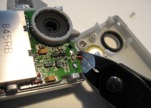
Step 7 - Remove unused parts like spring, rod, ball.
|
Schritt 7 - Ungenutzte Teile wie Feder, Stab und Kugel entfernen.
|
 |
|
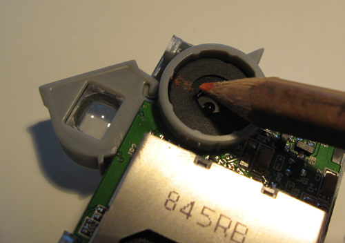
Step 8 - Now make a position mark on the lens. This avoids a nasty readjustment in case the focus is changed during the modification.
|
Schritt 8 - Jetzt eine Positionsmarkierung am Objektiv anbringen, dies verhindert eine lästige Justage falls der Fokus im Laufe des Umbaus verdreht werden sollte.
|
 |
|
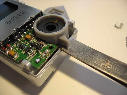
Step 9 - Remove focus lever.
|
Schritt 9 - Fokusring entfernen.
|
 |
|
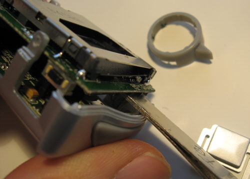
Step 10 - Loose (not remove at this point) the upper board from the lower one. Do not damage the oscillator on bottom of the board.
|
Schritt 10 - Die vordere Leiterplatte lösen (nicht entfernen an diesem Punkt). Auf den darunterliegenden Oszillator achten dass dieser nicht beschädigt wird.
|
 |
|
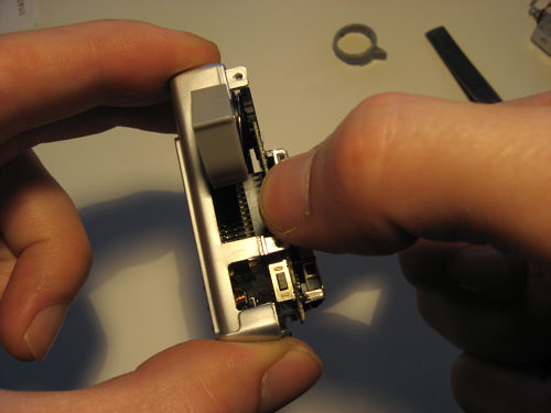
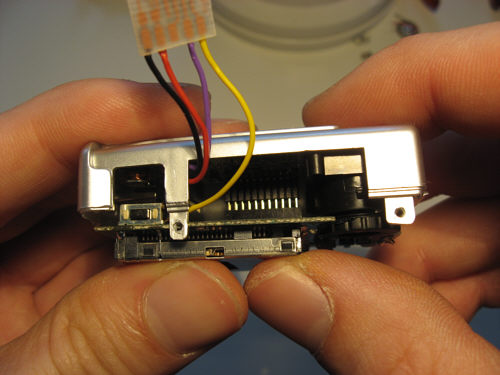
Step 11 - Remove now the upper board by picking it with both fingers in the middle and pull it straight up.
|
Schritt 11 - Die vordere Platine mit beiden Fingern in der Mitte greifen und gerade auseinanderziehen.
|
 |
|
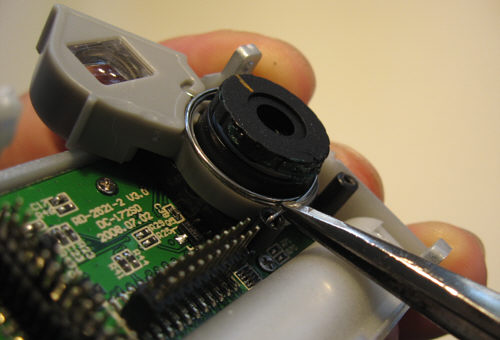
Step 12 - Remove viewfinder spring from lens holder.
|
Schritt 12 - Die Feder des Suchers lösen.
|
 |
|
Step 13 - Remove 3 screws that hold the circuit board.
|
Schritt 13 - Nun die 3 Schrauben an der Platine entfernen.
|
 |
|
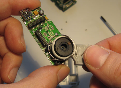
Step 14 - The board can be pulled up for removal. Don't rotate the lens
|
Schritt 14 - Die Platine kann dann nach oben herausgezogen werden. Objektivring nicht verdrehen.
|
 |
|
Step 15 - The viewfinder can now get removed.
|
Schritt 15 - Der Sucher kann nun entfernt werden.
|
 |
|
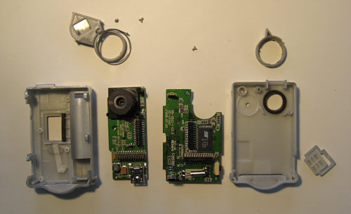
Step 16 - The camera is now disassembled and the modification can now start.
|
Schritt 16 - Die Kamera ist nun soweit zerlegt, jetzt geht es an den Umbau.
|
 |
|
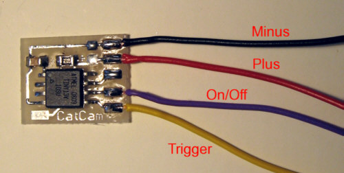
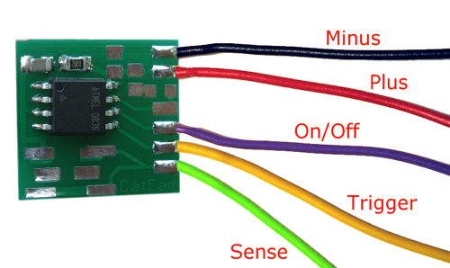
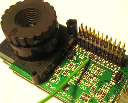
Step 17 - Solder the 4 or 5 wires to the controller board. The optimum length of the wires is around 1.6 inch. Controllers from September 2009 on are supporting the sense signal that increases the operating reliability as well as battery performance.
|
Schritt 17 - Die 4 bzw. 5 Kabel an die Steuerplatine löten. Die optimale Länge beträgt ca. 4cm. Controller ab September 2009 unterstützen die Rückleseleitung, um die Betriebssicherheit und Batterieleistung zu erhöhen.
|
 |
|
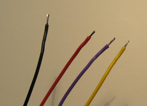
Step 18 - Strip the end of the wires and pre-solder them.
|
Schritt 18 - Die Enden der Kabel abisolieren und verzinnen.
|
 |
|
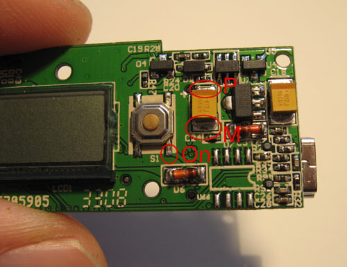
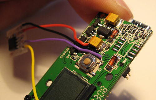
Step 19 - Solder 3 wires to the backside of the PCB with the lens. P = Plus (supply), M = Minus (ground), O = On/Off. It is best to put some solder on the marked locations prior to soldering the wires to them.
|
Schritt 19 - Drei Kabel nun an die Rückseite der Platine mit der Optik löten. P = Plus (Versorgung), M = Minus (Masse), O = Ein/Aus. Am besten die Lötpunkte zuvor etwas verzinnen bevor die Kabel daran angelötet werden.
|
 |
|
Step 20 - Bend the wires now in a way that they lead to the corner of the gap on the PCB.
|
Schritt 20 - Die Kabel nun so zurechtbiegen dass sie an die Ecke der Platinenaussparung laufen.
|
 |
|
Step 21 - Put the PCB back into the enclosure, bend the wires around the edge.
|
Schritt 21 - Die Platine nun zurück in das Gehäuse legen und die Kabel um die Ecke biegen.
|
 |
|
Step 22 - Screw the PCB back in.
|
Schritt 22 - Die Platine nun festschrauben.
|
 |
|
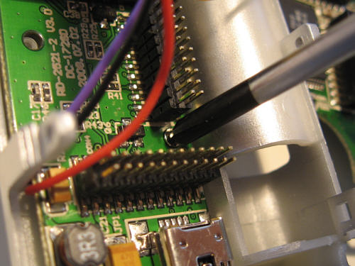
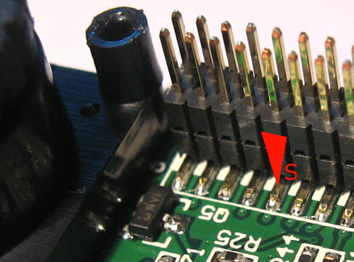
Step 23 - For the Sense signal wire locate the contact on the board with the lens. The 5th connector foot from the left is the right one. Heat it with the solder iron tip and apply a little bit of solder.
|
Schritt 23 - Für die Rückleseleitung (Sense) den Kontakt auf der Platine mit der Optik suchen. Es ist der 5. Fuss von links am Verbindungsstecker. Den Kontakt mit der Lötkolbenspitze erwärmen und etwas Lötzinn drauf verlaufen lassen.
|
 |
|
Step 24 - Solder the pre-soldered wire to the contact. Make sure no short is present to neighboring signals.
|
Schritt 24 - Das verzinnte Kabelende an den Kontakt löten. Sicherstellen dass keine Verbindung zu benachbarten Signalen vorhanden ist.
|
 |
|
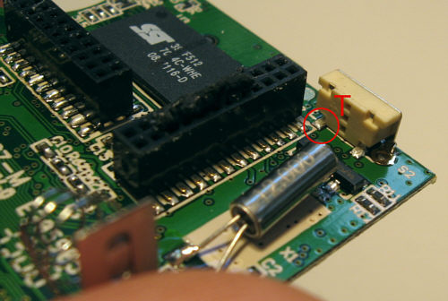
Step 25 - Locate the single solder spot on the trigger button on other PCB and put some solder on it. T = Trigger contact. Additionally, you may want to perform the Battery Hack
|
Schritt 25 - Auf der anderen Platine die Lötstelle am Auslöser lokalisieren und etwas verzinnen. T = Auslösekontakt. Zusätzlich kann nun der Batterie-Hack durchgeführt werden.
|
 |
|
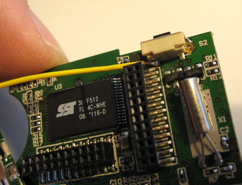
Step 26 - Solder the remaining wire to the trigger contact.
|
Schritt 26 - Das verbleibende Kabel am Auslösekontakt anlöten.
|
 |
|
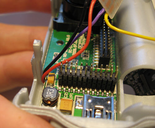
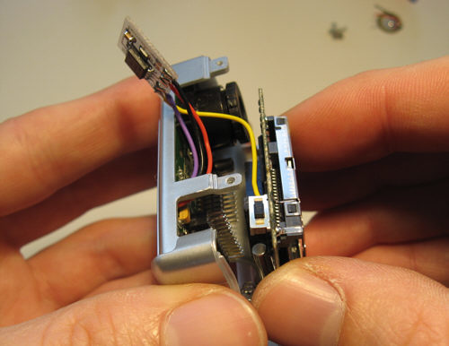
Step 27 - Put the two PCBs together, watch that the battery contacts are in the right place.
|
Schritt 27 - Die beiden Leiterplatten nun zusammenstecken und darauf achten dass die Batteriekontakte an der richtigen Stelle verlaufen.
|
 |
|
Step 28 - After making sure that the contacts in the camera are aligned push the PCBs together.
|
Schritt 28 - Nachdem sichergestellt ist dass die Pfostenleisten in der Kamera ineinander führen die beiden Leiterplatten zusammendrücken.
|
 |
|
Step 29 - Put the focus ring into the front enclosure and set the lever in the reference position.
|
Schritt 29 - Den Fokusring nun in die vordere Gehäusehälfte einsetzen und den Hebel in die Referenzposition bringen.
|
 |
|
Step 30 - Check that the lens is rotated into the reference position using the applied mark, then put the front enclosure with the focus ring back on.
|
Schritt 30 - Prüfen ob die Linse in ihre Referenzposition rotiert ist anhand der zuvor aufgebrachten Markierung. Dann die Vorderseite mit dem Fokusring aufsetzen.
|
 |
|
Step 31 - Assemble the camera.
|
Schritt 31 - Kamera zusammenschrauben.
|
 |
|
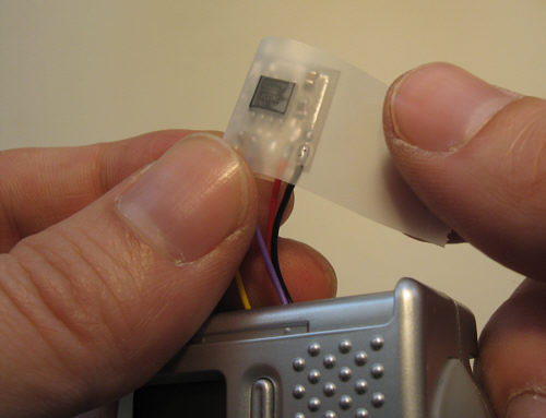
Step 32 - Insulate the controll chip with tape.
|
Schritt 32 - Den Controller mit Klebeband isolieren.
|
 |
|
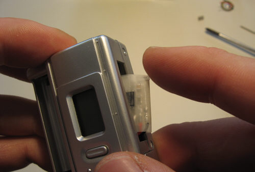
Step 33 - Put the controller in the camera.
|
Schritt 33 - Den Controller nun in die Kamera drücken.
|
|
|
Do now an electrical function test (Adjust time, take picture) then continue with the housing. If something is not working, check out the repair page.
|
Nun einen Funktionstest machen (Intervallzeit einstellen, Bild machen), anschliessend mit dem Gehäuse weitermachen. Wenn etwas nicht recht funktioniert die Reparaturseite besuchen.
|