 |
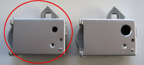
 Important note: This modification instruction applies to all VistaQuest VQ1005 prior to late 2008 (left model). Easy way to distinguish "new" from "old" is the diameter of the lens hole. With the late 2008 model the hole was increased from around 1/4 inch to 1/2 inch.
Modification instructions for the new model can be found here.
Safety note: Please work always with precaution. The camera can be damaged with electrostatic discharge. Touch only parts which you have to.
Never apply more force than necessary.
|
 Wichtiger Hinweis: Diese Umbauanleitung ist gültig für alle VistaQuest VQ1005 Kameras vor Herbst 2008 (linkes Model). Ein einfacher Weg zur Unterscheidung ist der Durchmesser der Linsenöffnung. Ab Herbst 2008 wurde dieses von ca. 5mm auf 10mm vergrößert.
Umbauanleitung fuer das neue Model findet sich hier.
Sicherheitshinweis: Immer vorsichtig arbeiten, die Kamera kann durch statische Entladung zerstört werden. Nur das anfassen was unbedingt sein muss.
Nie mehr Kraft aufwenden als unbedingt notwendig.
|
 |
|
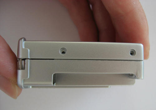
Step 1 - Remove screws from camera bottom.
|
Schritt 1 - Schrauben am Kameraboden lösen.
|
 |
|
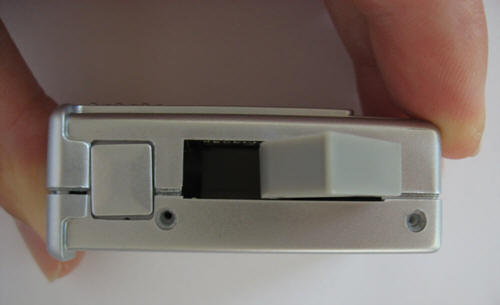
Step 2 - Remove screws from camera top.
|
Schritt 2 - Schrauben an der Kameraoberseite lösen.
|
 |
|
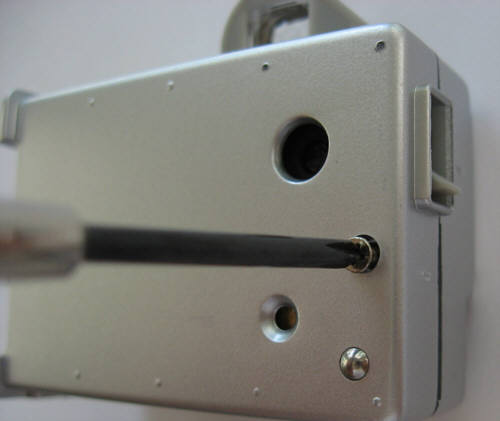
Step 3 - Remove long screw from front side.
|
Schritt 3 - Die lange Schraube auf der Vorderseite entfernen.
|
 |
|
Step 4 - Remember the position of the focus ring. Best is to bring the lever in a defined position before opening the camera.
|
Schritt 4 - Unbedingt die Position des Focusringes merken. Am besten den Hebel in eine eindeutige Position bringen bevor die Kamera geöffnet wird.
|
 |
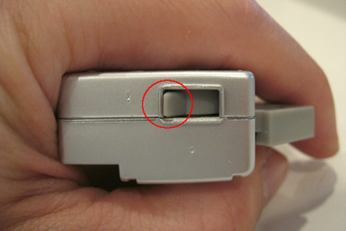
| Step 5 - Now some force is required. Pull both camera sides appart while bending the sides open and close . It will stick on the lens. Firmly pull until both parts are separated. It will help at the end that you pull the halfes on the USB interface appart. If you have problem open the camera refer to the next steps.
|
Schritt 5 - Jetzt ist etwas Kraft notwendig. Beide Kamerahälften unter leichtem hin- und herbiegen auseinanderziehen. Es wird am Objektiv etwas kräftiger kleben. Fest ziehen bis beide Hälften auseinander sind. Gegen Ende hilft es die Kamerahälften an der USB Schnittstelle auseinanderzubiegen. Wenn es Probleme gibt die Kamera zu oeffnen, dann die naechsten Schritte anschauen.
|
 |
|
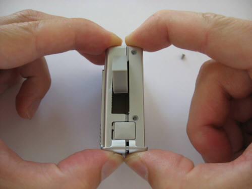
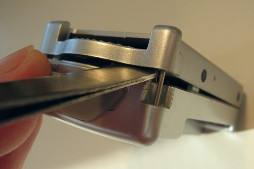
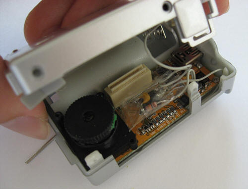
Step 5 - Sometimes the camera can not be opened easily. If thats the case pull the housing at the card slot side open and enter a flat screwdriver to separate the internal circuit boards (see next step).
|
Schritt 5 - Manchmal ist die Kamera nicht einfach zu oeffnen. Wenn dies der Fall ist dann das Gehaeuse an der Kartenschachtseite auseinanderziehen und mit einem flachen Schraubenzieher die inneren Leiterplatten auseinanderbiegen (siehe naechster Schritt).
|
 |
|
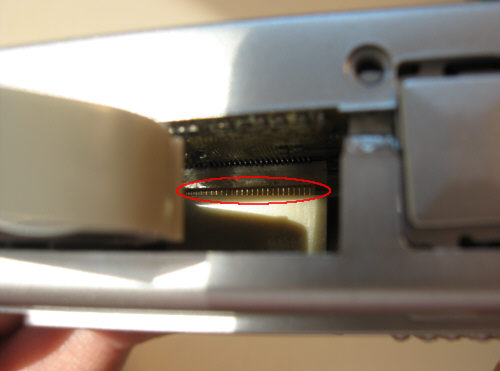
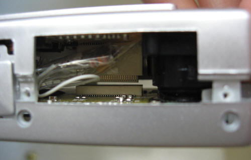
Step 6 - The circuit boards are separated when the board interconnector is more or less divided.
|
Schritt 6 - Die Leiterplatten sind getrennt wenn der Platinenzwischenstecker mehr oder weniger auseinandergezogen sind.
|
 |
|
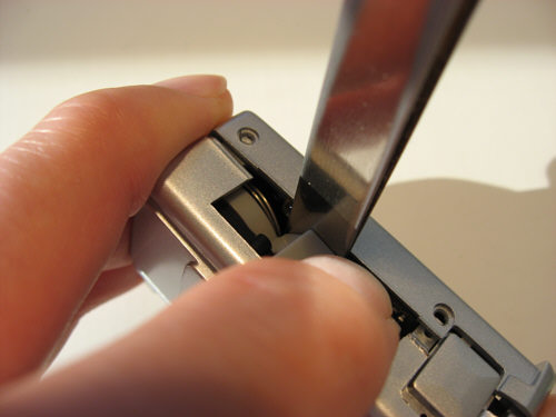
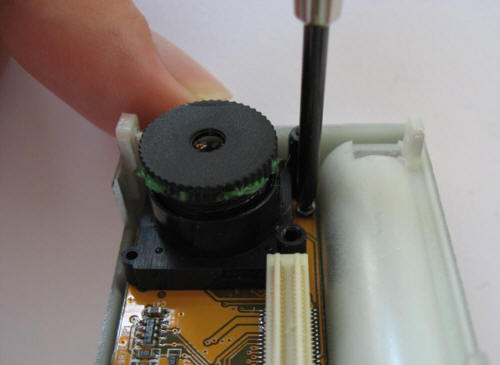
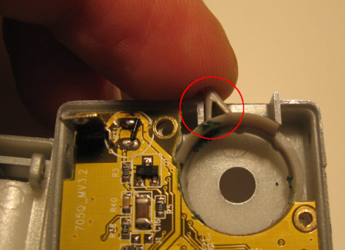
Step 7 - Now enter a flat and solid tool from the top close to the lens. Push the tool quick and firm into the direction that separates the housing parts. The glue at the lens will crack and the housing halfes will separate. If you have done this step please quickly check the repair description for tilted lens mount.
|
Schritt 7 - Nun einen flachen und festen Gegenstand von oben nahe der Linse einfuehren. Das Werkzeug schnell und fest in die Richtung druecken in der sich die vordere Gehaeuseschale loesen soll. Der Kleber an der Linse wird brechen und beide Gehaeusehaelften zerlegen. Wenn dieser Schritt durchgefuehrt wurde sollte nun kurz die Reparaturbeschreibung fuer verkippte Objektive angeschaut werden.
|
 |
|
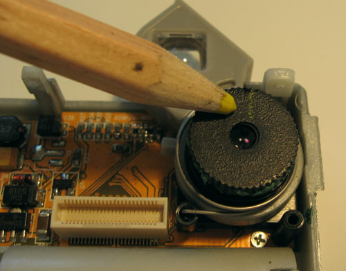
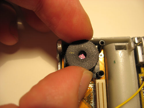
Step 8 - Now make a position mark on the lens. This avoids a nasty readjustment in case the focus is changed during the modification.
|
Schritt 8 - Jetzt eine Positionsmarkierung am Objektiv anbringen, dies verhindert eine laestige Justage falls der Fokus im Laufe des Umbaus verdreht werden sollte.
|
 |
|
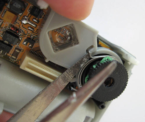
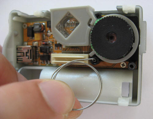
Step 9 - Now the spring of the viewfinder is going to be removed. Pull the spring out of the lock at the viewfinder.
|
Schritt 9 - Nun die Feder des Suchers entfernen. Dazu die Feder aushängen.
|
 |
|
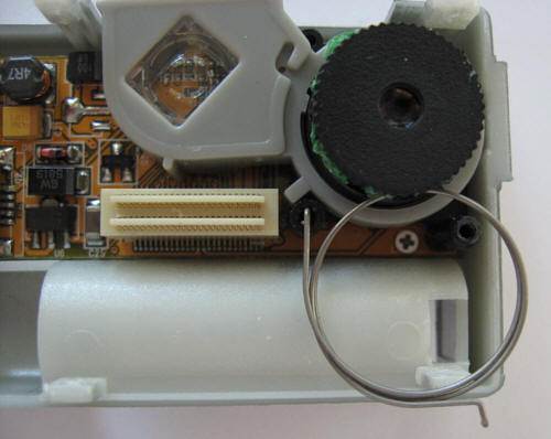
Step 10 - Lift the spring over the lens. Warning: Do not rotate the lens ! This will result in de-adjusted focus.
|
Schritt 10 - Die Feder jetzt über das Objektiv heben. Vorsicht: Objektiv nicht verdrehen ! Sonst wird der Fokus verstellt.
|
 |
|
Step 11 - Remove spring by bending a couple of times.
|
Schritt 11 - Feder entgültig durch mehrfaches hin- und herbewegen entfernen.
|
 |
|
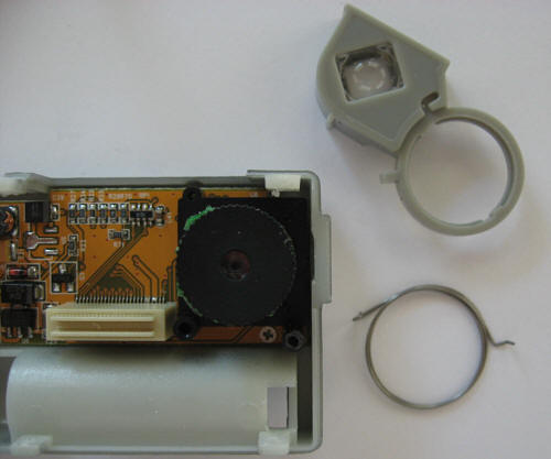
Step 12 - The viewfinder can now be removed.
|
Schritt 12 - Der Sucher kann nun ebenfalls entfernt werden.
|
 |
|
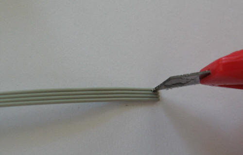
Step 13 - Now we prepare the wires to attach the controller. Using a cutter knife, the wires are separated from the ribbon cable. A short cut between the wires is mostly sufficient. If not, slide the blade along the ribbons of each cable, the separation will be easier.
|
Schritt 13 - Nun bereiten wir die Kabel zum Anschluss des Controllers vor. Dazu wird mit einem Teppichmesser zwischen den Einzeldrähten des Flachbandkabels ein kurzer Schnitt gemacht. Wenn dies kein sauberes Trennen der Adern erlaubt, dann mit der Klinge zwischen jeder Ader entlangfahren.
|
 |
|
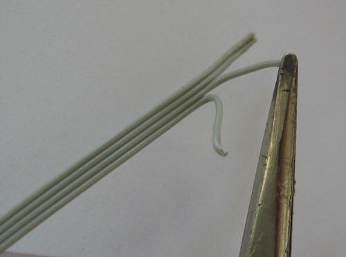
Step 14 - The single wires can be pulled appart using tweezers.
|
Schritt 14 - Die Einzeldrähte lassen sich dann mit einer Pinzette leicht auseinander ziehen.
|
 |
|
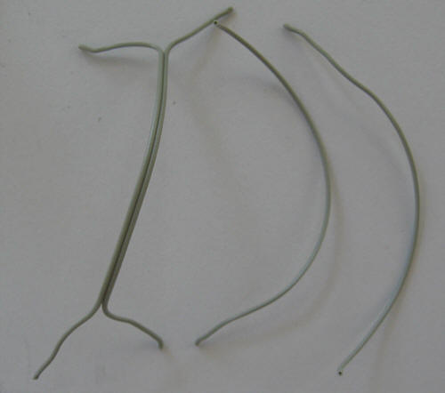
Step 15 - We need two individual wires and one double wire. Length approx. 1 1/2 inches.
|
Schritt 15 - Wir brauchen 2 einzelne Drähte und einen doppelten. Länge ca. 3-4cm.
|
 |
|
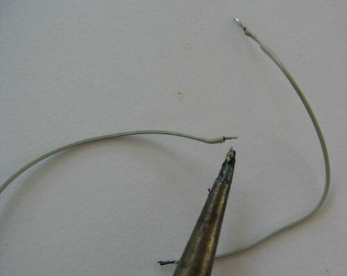
Step 16 - Tin the end of the wires. This eases the soldering to the camera.
|
Schritt 16 - Die Leitungsenden gleich Verzinnen, damit es sich später einfacher lötet.
|
 |
|
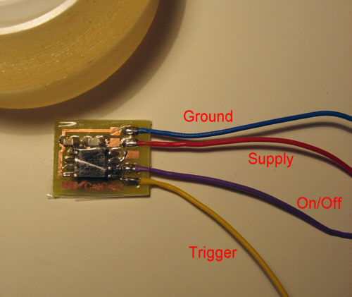
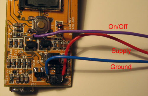
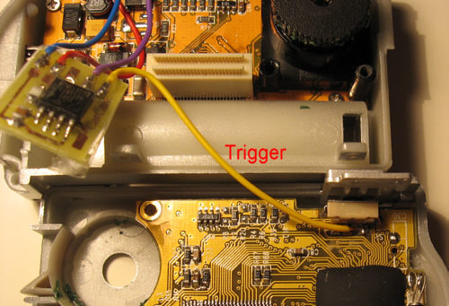
Step 17 - Solder the wires to the controller board. The above picture shows the positions, signal names and color coded wires for easier understanding of the next steps.
|
Schritt 17 - Die Kabel an das Controllerboard loeten. Das Bild oben zeigt die Positionen, Signalnamen und farbcodierte Kabel um die naechsten Schritte verstaendlicher zu machen.
|
 |
|
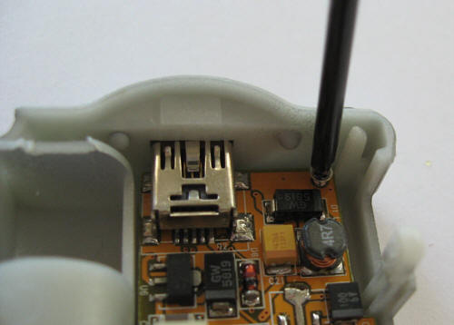
Step 18 - Now unscrew the camera board which carries the lens.
|
Schritt 18 - Nun die Platine welche das Objektiv trägt abschrauben.
|
 |
|
Step 19 - This board is fixed with 2 screws.
|
Schritt 19 - Diese Platine ist mit 2 Schrauben befestigt.
|
 |
|
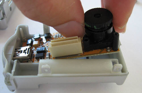
Step 20 - The board can be pulled up for removal. Don't rotate the lens.
|
Schritt 20 - Die Platine kann dann nach oben herausgezogen werden. Objektivring nicht verdrehen.
|
 |
|
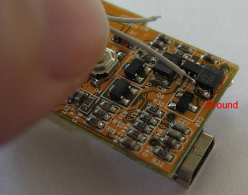
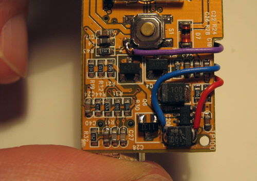
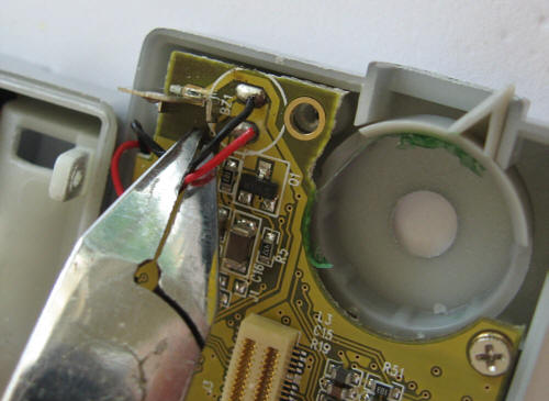
Step 21 - Place the board upside down. Don't touch anything unless necessary. Pay special attention to the display. The ground wire can now be soldered to the capacitor terminal. Tin this and all following solder joints before soldering the wires on.
|
Schritt 21 - Die Platine mit der Linse nach unten ablegen. Nichts anfassen was nicht unbedingt sein muss. Speziell auf das Display aufpassen. Die Masseleitung kann nun an den Kondensator gelötet werden. Diese und alle nachfolgenden Loetstellen erst verzinnen, dann Kabel festloeten.
|
 |
|
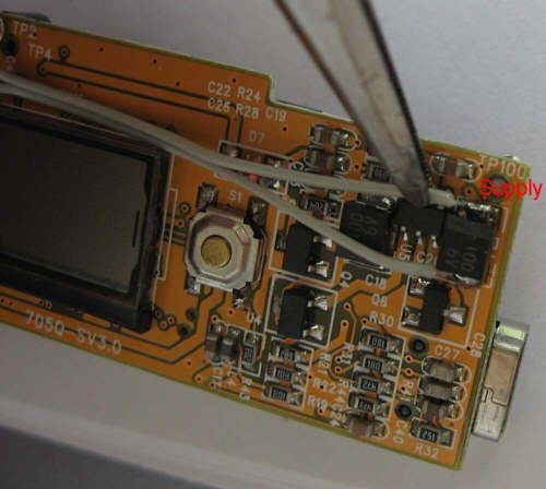
Step 22 - The supply wire can now be soldered to the other capacitor terminal.
|
Schritt 22 - Die Versorgungsleitung kann nun an den Kondensator gelötet werden.
|
 |
|
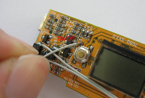
Step 23 - Solder one wire to the on/off button.
|
Schritt 23 - An den On/Off Taster wird nun ein Kabel gelötet.
|
 |
|
Step 24 - Place the wires on the board in a way that they are lying flat and pointing in the position shown in the picture.
|
Schritt 24 - Die Kabel auf der Platine anordnen, so dass sie möglichst flach aufliegen und sie in die im Bild gezeigte Richtung zeigen.
|
 |
|
Step 25 - Bend the wires around the board. Route them between the components so that they are flat on the surface.
|
Schritt 25 - Die Leitungen um die Platine biegen. Zudem die Leitungsfuehrung so gestalten, dass die Leitungen zwischen den Bauteilen verlaufen und flach auf der Oberflaeche aufliegen.
|
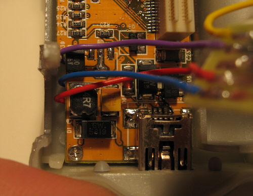 |
Step 26 - The board will be put back. Check now that the wires are not clamped between housing and board.
Now fix the board with 2 screws. Note: Start with the screw close to the lens. If there is no grip, push the board firmly down (e.g. at the lens bottom). If the board is not fixed tightly you will risk that the display is not operating well.
|
Schritt 26 - Die Platine wird nun wieder eingelegt. Jetzt darauf achten, dass die 3 Leitungen nicht eingeklemmt werden.
Nun die Platine mit 2 Schrauben befestigen. Anmerkung: Mit der Schraube neben der Linse beginnen. Wenn diese Schraube keinen griff bekommt dann die Platine kräftig nach unten drücken (z.B. am Fuss der Linse). Wenn die Platine nicht gut festgeschraubt ist riskiert man, dass das Display nicht richtig funktioniert.
|
 |
|
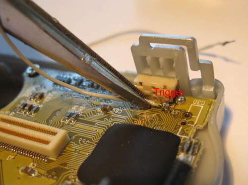
Step 27 - Solder now the Trigger signal wire from the controller to the trigger button.
|
Schritt 27 - Jetzt die Trigger-Signal Leitung vom Controller zum Auslöser loeten.
|
 |
|
Step 28 - You may want to disconnect the beeper. Additionally, you may want to perform the Battery Hack.
|
Schritt 28 - Piepser abklemmen. Eventuell möchten Sie den Batterie Hack durchführen.
|
 |
|
Step 29 - If necessary adjust the lens according to the previously made mark. This would also be the right time to check out the repair section.
|
Schritt 29 - Wenn notwendig die Linse entsprechend der zuvor gemachten Markierung justieren. Jetzt waere auch die richtige Zeit das Reparaturkapitel durchzuschauen.
|
 |
|
Step 30 - Also bring the focus lever in the defined position.
|
Schritt 30 - Ebenfalls den Fokusring in die definierte Position bringen.
|
 |
|
Step 31 - If not already done wrap the controller in tape so that all contacts are insulated. Then fold the halfes of the camera together.
|
Schritt 31 - Falls noch nicht gemacht den Controller in Tesafilm einwickeln, damit alle Kontakte elektrisch isoliert sind. Dann die beiden Kamerahälften übereinander legen.
|
 |
|
Step 32 - A difficult location is the board connector. Here the wires are caught easily. Sort wires with tweezers. Then press halfes together and screw in 5 screws.
|
Schritt 32 - Eine schwierige Stelle ist der Stecker zwischen den Platinen. Hier klemmen sich leicht die Kabel ein. Mit einer Pinzette Kabel sortieren. Dann die Hälften zusammendrücken und Gehäuse mit 5 Schrauben zusammenbauen.
|
|
|
Do now an electrical function test (Adjust time, take picture) then continue with the housing. If something is not working, check out the repair page.
|
Nun einen Funktionstest machen (Intervallzeit einstellen, Bild machen), anschliessend mit dem Gehäuse weitermachen. Wenn etwas nicht recht funktioniert die Reparaturseite besuchen.
|